General usage instructions
To build a profile u need to follow steps below:
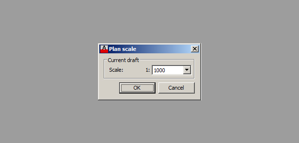
Specify the plan scale
Specify the plan scale by using the command QP_SCALE. When the command is entered, the application offers to select a scale.
The plan scale is unique for each drawing. It effects the interpretation of distance from AutoCAD units into meters.
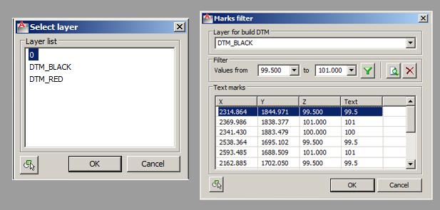
Create DTM
Create DTM by using the command QP_DTM. In the drop-down list  , specify a type of the entity from which data on the point and its height/elevation will be collected.
If DTM is created by the TEXT or MTEXT, the application will offer to select a layer where specified entities for the creation of DTM are to be found. The layer containing the selected entity will be automatically marked.
In this window the user can:
- filter collected marks;
- specify a layer for the creation of DTM;
- delete marks;
- preview the DTM which is being created.
DTM will be created on clicking “OK”. The layer where DTM is to be created can be set in the application settings.
Specify the profile section line
Draw the section line (route, pipeline, etc.) within the created DTM. The section line is specified by means of an AutoCAD POLYLINE or LINE.
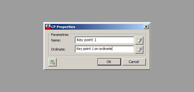
Draw CP
To mark characteristic points along the section line draw CP entities represented by BLOCKs with NOTEs.
When drawing CP the application inquires for a point on the section line (note: the point can be specified in any place but the application will consider only the points drawn with the use of object snap). Upon receipt of the point, the application offers to enter other parameters of CP: name on the plan drawing and caption on the profile ordinate.
The window can also be used to copy the text from the text entity (TEXT, MTEXT, ATTRIBUTE) already drawn in the drawing.
Create profile
Enter the command QP_PROFILE. The application inquires for specification of the profile section line which can be represented by an AutoCAD LINE or POLYLINE. After that, configure the created profile step by step in the “Profile wizard” window.
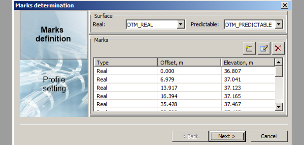
Step 1. Ground lines setting
As the real and predictable ground lines are drawn on the profile, appropriate DTM surfaces should be determined for the search of marks. A DTM surface is a set of graphic primitive elements 3DFaces on one and the same layer.
The upper drop-down lists contain all the layers of the drawing where 3Dfaces were found. The drop-down lists can be used to select real or predictable surface. After the selection of the surface, the list of the marks is filled with marks collected from the specified section line. The marks are determined at the vertexes of the section line and at the points of its crossing with 3Dfaces.
Note: When a layer is changed, the application conducts an automatic search of marks along the section line and fills the list of marks for the appropriate ground line type deleting previous marks of the given type.
To continue creating the profile, click on the “Continue” button.
Step 2. Setting the profile
At the next step of the “Profile Wizard” the user can configure the view and design of the created profile.
The profile design includes:
- Profile name which is drawn above the profile frame;
- Scalebar with the ground levels;
- Vertical and horizontal scales used to interpret the distance from meters into AutoCAD units;
- Reference level, which is the lowest mark of the profile.
Press “continue”.

Step 3. Configure the prof
Use the last page of the Profile Wizard to configure the table.
A template is used to set the profile table. Table templates are presented in the left list of the window. The application offers three initial templates by default, also allows to create new ones and delete the existing ones.
Each template consists of parts presented in the right list. The toolbar is used to create, edit or delete parts and change their position in the table. Note: the sequence of parts in the list corresponds to the sequence of parts in the profile table.
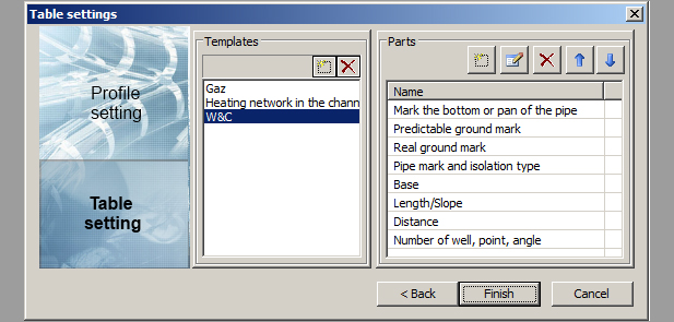
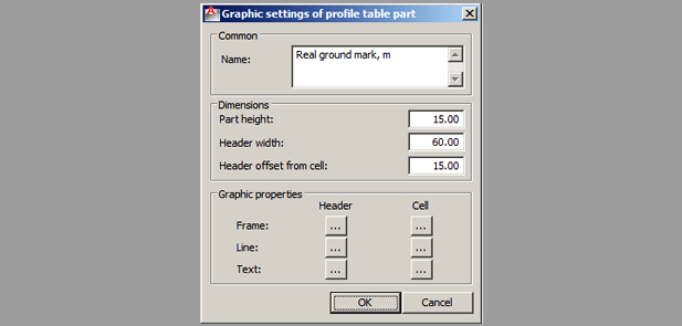
During editing a profile part, the user can specify a name and graphic settings.
Upon clicking on the “Finish” button, the application inquires for the point of the profile insertion which is the lowest left hand corner point of the profile frame.
Draw ordinate
To drawn a custom ordinate on the created profile, use the command QP_ORDINATE. The application inquires for a point inside the profile frame, where the ordinate will be drawn. Upon receipt of the point, the application offers to enter other parameters of ordinate with help of window on diagram 4.
Note: if profile has no ground line, then ordinate won’t be drawn.
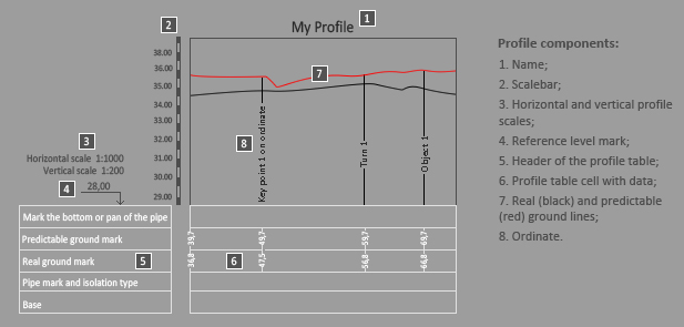
Profile components:
- Name;
- Scalebar;
- Horizontal and vertical profile scales;
- Reference level mark;
- Header of the profile table;
- Profile table cell with data;
- Real (black) and predictable (red) ground lines;
- Ordinate.